5.

FLOW OF GASES AND STEAM THROUGH DIFFUSERS

–   page 5.3   –
–   page 5.3   –
 Problem 407: Calculation of h-s chart of compression in diffuser of radial compressor, see art. [Škorpík, 2022]
–   page 5.5   –
 Problem 456: Calculation of cone diffuser and its pressure gradient  Problem 441: Calculation of cone diffuser with constant pressure gradient
–   page 5.8   –
–   page 5.10   –
–   page 5.10   –
–   page 5.12   –
 Problem 388: Design of diffuser profile cascade for axial fan, see art. [Škorpík, 2022b]
–   page 5.13   –
 Problem 410: Injector dimensions calculation
–   page 5.15   –
–   page 5.17   –
–   page 5.18-28   –
–  Online shop  –
If you found this article helpful, you can purchase the full version in my online shop. Thank you for your support, and I wish you every success with your projects.

Jiří Škorpík
author
FLOW OF GASES AND STEAM THROUGH DIFFUSERS
page 5.2
– author: –
ŠKORPÍK, Jiří (LinkedIn.com/in/jiri-skorpik)
–    issue date:    –
April 2016, June 2023 (2nd ed.)
– title: –
Flow of gases and steam through diffusers
– proceedings: –
– provenance: –
Brno (Czech Republic)
– email: –
skorpik.jiri@email.cz

Copyright©Jiří Škorpík, 2016-2023
All rights reserved.

FLOW OF GASES AND STEAM THROUGH DIFFUSERS
page 5.3

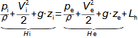
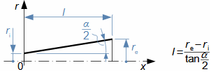
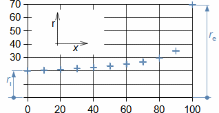
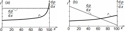
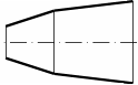
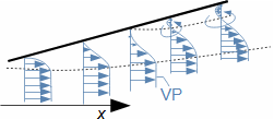
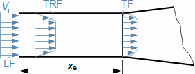
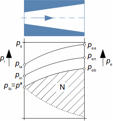
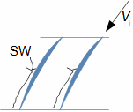
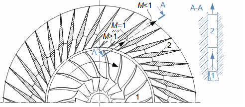
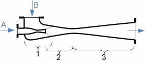
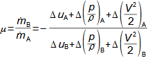
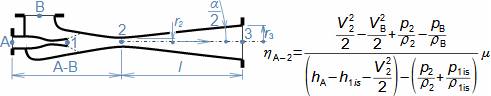
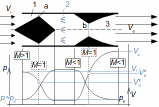
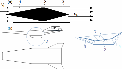
What are diffusers and applications of diffuser theory

A diffuser is a channel with a continuously changing flow cross-section. Fluid flow in the diffuser is a process that primarily involves an increase in pressure and a decrease in kinetic energy. According to Hugoniot theorem, a different shape of diffuser is suitable for supersonic inlet velocities than for subsonic inlet velocities. In the case of supersonic inlet velocity, the flow must first slow down to the speed of sound in the tapering part of the diffuser, see Figure 374.

– 374: –
Two basic types of diffusers
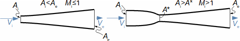
left-diffuser for subsonic speeds; right-diffuser for supersonic speeds. A [m2] diffuser flow area; V [m·s-1] gas velocity; M [Mach] Mach number; A* [m2] critical cross-section of supersonic diffuser in which gas reaches speed of sound (critical state). The index i denotes the state at the inlet of the diffuser, the index e denotes the state at the outlet of the diffuser.
Application of diffuser theory
Diffuser theory has wide application in various types of current machines with diffuser channel shapes. The sophisticated diffuser theory can be used to describe even, at first sight, very complex flows, for which a large amount of measured data is available for different diffuser shapes.

Energy parameters of diffusers

The energy parameters of diffusers, such as the values ​​of state quantities, mass flow, critical velocity and efficiency, can be determined from the energy balance of the gas in the h-s chart of the diffuser, from which most of the quantities can be directly read. Many calculation procedures can be taken from the nozzle calculations given in the article Flow of gases and steam through nozzles. The energy balance of a diffuser during liquid flow can be obtained using the Bernoulli equation.

  ~  
h-s chart of gas compression in diffuser
The compression in the diffuser is affected by energy dissipation or losses. An h-s chart can be used to identify the actual gas states as it flows through the diffuser and the losses, where the comparative (ideal) process is an isentropic compression with the same pressure and velocity at the outlet as the actual compression, see Figure 1274, pp. 5.4. The pressure loss Lp is then defined as the loss between the total outlet and inlet pressure of the diffuser. To overcome the loss Lp and achieve the same pressure as in lossless compression, the kinetic energy at the diffuser inlet must be increased by just the value of Lh.
FLOW OF GASES AND STEAM THROUGH DIFFUSERS
page 5.4
– 1274: –
Change of gas state in supersonic diffuser
left-chart of h-s subsonic diffuser; right-chart of h-s supersonic diffuser. h [J·kg-1] gas enthalpy; h* [J·kg-1] critical enthalpy; p [Pa] gas pressure; s [J·kg-1·K-1] entropy; t [°C] gas temperature; V* [m·s-1] critical velocity; Lh [J·kg-1] diffuser loss; Lp [Pa] pressure loss. The index s indicates the total gas state, the index is the isentropic compression.
  ~  
Mass flow through diffuser
The mass flow of gas through the diffuser depends on the size of the smallest diffuser flow area, which is the inlet flow area Ai for subsonic and the critical diffuser flow area A* for supersonic, see Figure 374, pp. 5.3. The mass flow is then calculated from the continuity equation for the gas parameters at this flow area.
  ~  
Critical velocity in diffuser
The critical velocity V*in actual compression is the same as in isoentropic compression, because the speed of sound in an ideal gas is a function of temperature only and the isotherms correspond to the isoenthalps in the h-s chart. This means that the transition from supersonic to subsonic flow in real compression occurs at a lower pressure than in isentropic compression p*<p*is. This is due to the lower gas velocity at the diffuser walls than at the core of the flow, therefore the mean gas velocity may already be sonic at pressure p*while it is still supersonic at the core of the flow. The above facts mean that the gas reaches the critical velocity - meaning the mean flow velocity - already before the narrowest point of the diffuser.
  ~  
Diffuser efficiency
Diffuser efficiency can be defined in different ways. Most often it is the ratio between the difference in enthalpies at isentropic and actual compression, as these states are the easiest to detect, see Equation 405.
– 405: –
Diffuser efficiency
η [1] diffuser efficiency defined to static gas states (efficiency determined to total enthalpy states will have a higher value, as can be seen from the h-s chart).
FLOW OF GASES AND STEAM THROUGH DIFFUSERS
page 5.5
Similarity in diffuser efficiencies
Similar diffusers under similar operating conditions will also have similar efficiencies and because it is the similarity coefficient. This similarity can be used in the design of a new diffuser to predict its parameters based on an estimate of its efficiency. The accuracy of such a design depends on the degree of similarity of the diffusers being compared.
  ~  
Energy balance of diffuser at liquid flow
In the case of liquids or insignificant changes in gas density, the energy balance of the diffuser is based on Bernoulli equation. In the diffuser, the liquid does not do any external work, so the total energy of the liquid in front of the diffuser must be equal to the total energy of the liquid at the outlet of the diffuser plus losses, see Formula 415.
– 415: –
Energy balance of the diffuser during fluid flow
g [m·s-2] gravitational acceleration; Hi, e [J·kg-1] head of fluid at inlet or outlet; z [m] height of diffuser axis from reference plane; ρ [kg·m-3] density.
Hydraulic efficiency of diffuser
In these cases, the diffuser efficiency, referred to as the hydraulic efficiency, can be defined as the ratio between the total energy of the fluid at the outlet and the inlet of the diffuser (Formula 411).
– 411: –
Hydraulic efficiency of diffuser
 

Diffuser shapes

In practice, only two diffuser shapes are used. The simplest shape is the conical diffuser with a constant diffuser angle. The other diffusers, also known as cornut diffusers, have a variable angle diffuser depending on the pressure gradient requirement of the diffuser.

  ~  
Pressure gradient in diffuser
The properties of diffusers depend on the pressure gradient distribution in the diffuser, which can be determined for the case of lossless flow and ideal gas using Equation 432. In the case of actual processes, the pressure gradient can be calculated using thermodynamic data of real gases, see Problem 441, pp. 5.7.
– 432: –
Pressure gradient in diffuser
κ [1] ratio of heat capacities. The derivation of this equation is given in Appendix 432. The equation is derived under the simplifying assumption that the flow velocity has only an axial direction throughout the cross section and for an ideal gas.
FLOW OF GASES AND STEAM THROUGH DIFFUSERS
page 5.6
  ~  
Conical diffusers
The conical shape of the diffuser (Figure 458) is easy to produce, even in the case of non-circular variants. According to [Dejč, 1967, p. 391], the diffuser angle α ranges from 6 to 15°, while most diffusers are produced with the diffuser engle in the middle range of 10 to 12°.
– 458: –
Cone diffuser
r [m] radius; α [°] diffuser angle; l [m] diffuser length; x [m] distance on axis.
Flow separation from walls of conical diffusers
The very rapid pressure drop at the inlet of the cone diffusers causes that there is already a very small pressure gradient (see Problem 456) or very low flow energy at the end of the diffuser. This causes an increased probability of flow separation from the diffuser walls. This is a disadvantage of cone diffusers.
–  Problem 456:  –
Calculate the angle of a conical diffuser and determine the pressure gradient across this diffuser if it has a length of 100 mm and initial radius of 20 mm. Inlet parameters of the diffuser: 82 m·s-1, 110 kPa, 20 °C, dry air. Outlet parameters: 114 kPa. Consider a lossless flow. The solution to the problem is given in Appendix 456.
Pressure gradient of cone diffuser
grad p [kPa·m-1] pressure gradient; x [mm].
  ~  
Cornut diffusers
Diffusers with the variable diffuser angle α are called cornut diffusers and are designed for the required pressure gradient. Most often, cornut diffusers are designed for a constant pressure gradient (Figure 430a, pp. 5.7) or a linear pressure gradient (Figure 430b, pp. 5.7).
FLOW OF GASES AND STEAM THROUGH DIFFUSERS
page 5.7
–  Problem 441:  –
Design a cornut diffuser of circular cross-section corresponding to the requirement dp/dx=const. Diffuser inlet parameters: 82 m·s-1, 110 kPa, 20 °C, dry air. Diffuser outlet parameters: 114 kPa. The required diffuser length is 100 mm with inlet radius of 20 mm. Consider diffuser efficiency of 93 % with uniformly distributed losses. The solution to the problem is given in Appendix 441.
Image for Problem 441
Calculated radius of diffuser with constant pressure gradient - so-called cornut shape [Frass, 1989, p. 156]. r [mm]; x [mm].
– 430: –
Two basic shapes of cornut diffusers
Diffuser with linear pressure gradient change
(a) diffuser with constant pressure gradient, see its calculation in Problem 441; (b) diffuser with linear decrease in pressure gradient.
Flow separation from walls of cornut diffusers
Cornut diffusers have a sharp widening at the outlet (see Problem 441), so they can be expected to be more sensitive to boundary layer separation from the wall than cone diffusers. Measurements show that this is the case for long diffusers, but the opposite is true for short diffusers (cone diffusers with α>18°) [Dejč, 1967, p. 392].
Diffusers with constant pressure gradient
Diffusers with the constant pressure gradient (Figure 430a) also have a more uniform velocity profile than cone diffusers and are therefore also used upstream of coolers or heat exchangers with the requirement for uniform distribution of mass flux over the flow area of the exchanger [Goroščenko, 1952, p. 67], [Frass, 1989, p. 155].
Diffusers with linear pressure gradient
In the diffuser designed to linearly decrease the pressure gradient (Figure 430b), the pressure gradient decreases gradually as the boundary layer energy decreases (approximately linearly), and is therefore the shape with the lowest probability of flow separation [Dejč, 1967, s. 388].
Practical solutions for cornut diffusers
Continuous shape changes of diffusers with variable diffuser angles are difficult to manufacture and are therefore replaced by a combination of two or more conical diffusers with different diffuser angles, see Figure 831, pp. 5.8, [Dejč, 1967, s. 393].
FLOW OF GASES AND STEAM THROUGH DIFFUSERS
page 5.8
– 831: –
Practical solutions for variable widening diffusers
 

Flow separation

In diffusers, losses are caused by internal friction, possibly by shock waves, and by the loss due to the boundary layer separation from the diffuser walls. The process of boundary layer separation from the wall is shown in Figure 418. Boundary layer separation occurs as a result of the total pressure in the boundary layer dropping below the static pressure behind the diffuser. At this point, the working fluid backflows along the diffuser wall and the boundary layer is separated from the wall. The total pressure drops in the boundary layer due to the loss of kinetic energy of the flow. However, the kinetic energy of the fluid in the boundary layer can be increased by various methods. The loss due to boundary layer separation results in an increase in diffuser pressure loss.

– 418: –
Mechanism of boundary layer separation from wall and subsequent vortex formation
Mechanism of boundary layer separation from diffuser wall and subsequent vortex formation
  ~  
Increasing kinetic energy in the boundary layer using turbulence
The loss at flow seapration is greater the further away from the end of the diffuser the separation occurs. The position of the separation can be influenced, for example, by increasing the turbulence in the diffuser, because the energy and momentum of the stream core is shared with the boundary layer, an effect that is absent in laminar flow. If it is required to achieve turbulent flow, then it is necessary to ensure that the flow is already fully developed at the diffuser inlet. This is most often achieved by embedding a vortex generator or throat in front of the diffuser in which the boundary layer develops to turbulence, see Figure 428.
– 428: –
Development of velocity profile in diffuser throat
LF-laminar flow region; TRF-transition flow region; TF-fully developed turbulent flow. xe [m] minimum diffuser throat length for full boundary layer development.
FLOW OF GASES AND STEAM THROUGH DIFFUSERS
page 5.9
Increasing kinetic energy in the boundary layer using centrifugal force and suction
The boundary layer can also be stabilised by the tangential velocity component and the centrifugal force will cause a higher pressure at the diffuser walls - in the case of a potential vortex, a nearly stationary core is formed in the axis of the diffuser, which in the case of liquids is filled with saturated vapour. Typical examples are water turbine draft tubes, in which a small tangential component of the flow at the turbine outlet. The flow at the outlet of the diffuser can also be stabilised by suction gas through openings in the diffuser walls, etc (see [Japikse and Baines, 1995]).
  ~  
Pressure loss in diffusers
The flow separation will also affect the magnitude of the pressure loss Lp of the diffuser (see Equation 1274, pp. 5.4 for definition). Pressure loss is also a function of diffuser length and diffuser angle.
Effect of cone diffuser angle on pressure loss
Figure 631 shows the dependence of the pressure loss Lp of the diffuser with the change of the diffuser angle α. This pressure loss is compared with the pressure loss at the flow through two connected channels without a diffuser (α=90°). In this way, it is possible to evaluate up to which diffuser angle it makes sense to use diffusers and when not to use it. According to Figure 631, the pressure drop of the cone diffuser from a certain angle can be greater than that of the flow through two connected channels without a diffuser. This is due to the fact that the internal friction loss decreases with the diffuser angle α, but the vorticity loss at boundary layer separation increases with the angle α. Thus, in a flow through two connected channels without a diffuser, only the vortices at separation are generated [Maštovský, 1964, p. 88], which cause an increase in entropy by the same mechanism as in the throttling of the flow through the orifice.
– 631: –
Effect of cone diffuser angle on pressure loss
A scale chart is given in [Dejč, 1967, p. 382].
Solutions for short diffuser shapes with regard to pressure loss
If it is necessary to shorten the diffuser, it is more cost effective to use the combination shown in Figure 427 than to increase the diffuser angle. This solution can be likened to a smooth cornut diffuser on Figure 430a, pp. 5.7.
– 427: –
Practical solutions for space-constrained diffusers
FLOW OF GASES AND STEAM THROUGH DIFFUSERS
page 5.10

Supersonic diffusers

The design of the supersonic diffuser is problematic. Ideally, the compression in the diffuser should be through compression waves, which are the opposite of expansion waves. The compression waves should occur in the convergent part of the diffuser, which corresponds to the inverted ideal Laval nozzle designed by the method of characeteristics. However, such supersonic diffusers are not produced because in real flow, oblique shock waves are already generated at the inlet edges of the diffuser and others inside the convergent part [Dejč, 1967, p. 405]. Instead, stepped designs of convergent sections of supersonic diffusers are preferred.

Supersonic diffusers with stepped convergent section
In realistic conditions, the best flow stability is achieved by supersonic diffusers that have stepped flow deceleration (Figure 552). These are shaped to produce successive oblique shock waves at certain points with progressively greater slope, so that the last wave at the narrowest point of the diffuser is normal. Supersonic stepped diffusers are easy to design because the behaviour of oblique shock waves is well studied and described. Thus, in these cases, the losses that shock waves can cause are always taken into account. The diffusers in Figure 552 are jet engine diffusers and ensure that subsonic flow will enter the engine even during supersonic flight.
– 552: –
Supersonic diffusers with stepped flow deceleration
(a) stepped supersonic diffuser; (b), (c) stepped supersonic diffuser with following shock waves-as if reflected from diffuser wall- which inherently directs velocity vector in axial direction and reduces losses [Dejč, 1967, p. 409]. SW-shock waves.

Non-design diffuser conditions

Each diffuser is designed for a specific gas state in front of and behind the diffuser. If this state changes, the flow in the diffuser will change. Such a state is called a non-design state. In non-design conditions, the diffuser efficiency decreases (especially at lower flow rates, the loss due to boundary layer separation from the walls increases) and the diffuser may even turn into a Laval nozzle.

FLOW OF GASES AND STEAM THROUGH DIFFUSERS
page 5.11
Non-design states of subsonic diffusers
Figure 554 shows the two non-design conditions of the subsonic diffuser, denoted by a, b (index n indicates the design condition). These non-design conditions are induced by a change in the inlet velocity Vi for the same inlet stagnation pressure, where Via<Vin<Vib=a. The velocity Vib is sonic respectively critical. For each case, the backpressure also changes, if it were still the same (pe=pen), there would be no flow equilibrium. If we want to maintain backpressure, then we need to use inlet flow control-such a typical application is a diffuser valve. At less than the critical pressure p* a shock wave is generated behind the narrowest cross-section and, in addition, when the backpressure drops below pec, the diffuser becomes a Laval nozzle, see Hugoniot theorem.
– 554: –
Effect of inlet velocity change on function of subsonic diffuser
N-area function of Laval nozzle.
Non-design states of supersonic diffusers
Figure 654 shows two non-design conditions of the supersonic diffuser, denoted by a, b (index n denotes the design condition), with Via<Vin<Vib>a. For each case, the backpressure is also varied so that the subsonic section of the diffuser does not produce a shock wave.
– 654: –
Effect of inlet velocity change on supersonic diffuser function
In the case-a, the convergent section of the diffuser is not able to accommodate such a large amount of gas, so a normal shock wave will be generated before the diffuser, which will increase the pressure to supercritical and reduce the velocity to subsonic – convergent part act as a nozzle and the divergent section of the diffuser will function as a Laval nozzle in the non-design condition.
FLOW OF GASES AND STEAM THROUGH DIFFUSERS
page 5.12
Using a fixed throat of a supersonic diffuser to create stable conditions for its operation
The ability to change the back pressure or control the flow area is a prerequisite for the operation of a supersonic diffuser over a wide range of input parameters. The mechanism to control the flow area is not used up to the inlet velocity of about M<1,5 Mach - only the diffuser throat with a constant cross-section is in front of the diverging section of such a diffuser, similar to the one shown in Figure 428, pp. 5.8. In this design, it is assumed that a normal shock wave is generated at the inlet of the throat, in which the velocity is reduced to subsonic [Dejč, 1967, p. 406]. The losses in such a throat will, at these velocities, still not be significant. More demanding experiments with variable backpressure diffusers, in which shock waves are deliberately generated, are given in [Dejč, 1967, pp. 410-415].

Diffuser profile cascades

Figure 745 shows that the diffuser profile cascades will have similar characteristics to the cornut diffusers. However, converting the shape of a diffuser profile cascade to an equivalent symmetrical diffuser is problematic. The simple geometric conversion of Figure 745 may not, in terms of flow properties, always be sufficiently predictive. In addition, the sensitivity to boundary layer separation is increased by the cross pressure gradient that arises in the curved channels, hence the low curvature of the profiles in the diffuser cascades.

– 745: –
Geometric similarity of diffuser blade cascade with symmetrical diffuser
Formation of a λ-shock wave in compressor profile cascade
If the inlet velocity at the inlet to the diffuser profile grille reaches or exceeds the critical Mach number, then the flow exceeds the speed of sound on the suction side of the profile. However, at the outlet of the diffuser channel the pressure is higher than at the inlet, and so is the flow area, so according to Hugoniot's theorem there must be a abrupt change from supersonic to subsonic velocity, this happens locally near the profile in a λ-shock wave, see Figure 864, pp. 5.13. A measure to reduce the effect of such a shock wave is described in [Kadrnožka, 2004, p. 136].
FLOW OF GASES AND STEAM THROUGH DIFFUSERS
page 5.13
– 864: –
Formation of a λ-shock wave in compressor profile cascade
Supersonic profile cascades for compressors
Supersonic profile cascades are rarely used due to their low efficiency and poor controlled operation. Their use is justified, for example, in single-stage compressors with very high compression ratios, see Figure 770.
– 770: –
Example of supersonic turbocompressor arrangement
1-radial compressor impeller; 2-diffuser blades with supersonic profile.

Ejectors and injectors

Ejectors and injectors are jet machines that are used as vacuum pumps or pumps. The function of ejectors or injectors is based on transferring part of the kinetic energy of the driving fluid to the fluid being drivenin the mixing zone. This happens approximately at the neck of the diffuser, see Figure 112, where the driven fluid is drawn into the jet of the driving fluid, the whole process being accompanied by relatively high losses manifested by an increase in the internal thermal energy of the working fluid. In the diffuser section of the machine, kinetic energy is transformed into pressure energy. The difference between an ejector and an injector is that the pressure at the outlet of the ejector is lower than the pressure of the driving fluid at the inlet. In contrast, the pressure at the outlet of the injector is higher than the pressure of the driving fluid.

– 112: –
General chart of ejector or injector
A-driving fluid; B-driven fluid; 1-inlet zone; 2-diffuser neck (mixing zone); 3-outlet diffuser.
FLOW OF GASES AND STEAM THROUGH DIFFUSERS
page 5.14
  ~  
Energy transformation in mixing zone
The shape of the diffuser neck must be designed to gradually transfer the kinetic energy to the driven fluid and balance the velocity field. There must also already be a transformation of kinetic energy into pressure energy in the diffuser neck, this contributes to the stabilization of the velocity field and at the same time reduces the internal friction in the diffuser, which is a function of the flow velocity. So, the pressure at the inlet to the diffuser section will be greater than the pressure at the inlet of the driven fluid.
Ejection ratio in mixing zone
The ratio between the mass flow of the driven and driving fluid, referred to as the ejection ratio, can be determined from the energy balance of mixing in the diffuser neck, see Equation 404.
– 404: –
Energy balance of ejectors and injectors
u [J·kg-1] internal thermal energy of 1 kg working fluid; μ [1] ejection ratio [Dejč, 1967, p. 419]. The derivation of the equation neglecting the effect of the potential energy change is given in Appendix 404. The calculation of the ejector and injector is also carried out in [Hibš, 1981], [Dejč, 1967], [Kadrnožka, 1984], [Nechleba and Hušek, 1966].
  ~  
Increase in internal thermal energy
The internal thermal energy in a jet pump is increased due to losses (kinetic energy or pressure transformation to thermal energy) or heat sharing between the driving and driven fluid. The greatest change in internal thermal energy occurs when one of the working fluids condenses in the neck space. A typical example is the jet feed pump of a steam boiler, see Problem 410, pp. 5.15.
  ~  
Using ejectors
Ejectors are widely used in industry. They are used for pumping liquids from great depths in the mining industry [Nechleba and Hušek, 1966, p. 218], in the power industry for suction of steam-air mixture from the condenser of steam turbines where the driving fluid is steam (Figure 699).
– 699: –
Example of ejector as steam condenser vacuum cleaner
Example of steam ejector in function as a steam condenser vacuum cleaner
[Nožička, 2000]
FLOW OF GASES AND STEAM THROUGH DIFFUSERS
page 5.15
  ~  
Example of using injector as feed pump
Injectors are used as feed water pumps for steam boilers of steam locomotives. The water is pumped to higher pressure using the steam injector, which has an inlet pressure lower than the outlet pressure of the diffuser pe. This is possible because of the very high kinetic energy the steam can gain in the nozzle during expansion, see Problem 410. The steam transfers this kinetic energy to the water in the mixing chamber (neck of diffuser) and condenses at the same time. A necessary condition for the operation of such a pump is that the vapour still condenses in the neck of the diffuser, or that only liquid without vapour bubbles flows through the diffuser, otherwise the required pressure cannot be achieved. The driving vapour will completely condense in the diffuser neck if an adequate amount of cold water is added. This means that the pump performance decreases with the temperature of the intake water.
–  Problem 410:  –
Design the basic dimensions of the injector (fluid-dynamic pump) for steam boiler. The feed water is pumped from an open tank at 70 °C to a pressure of 0,54 MPa. The required feed water flow rate is 60 kg·h-1. The efficiency of the diffuser section is considered to be 80 %. The nozzle efficiency value includes the efficiency of transfer of kinetic energy from the steam to the pumped water and is 10 %. The saturation steam speed at the pump inlet is 20 m·s-1. The speed of the water at the inlet and outlet of the pump is 3 m·s-1. Do not consider pressure losses in the boiler and in the piping. The solution to the problem is given in Appendix 410.
Steam injector
ηA-2 [1] expansion efficiency in nozzle and momentum transfer in mixing chamber (derivation in Appendix 410, §4).

Ram-powered engines

Ram-powered engines use the supersonic diffuser in the engine mouth to compress air during supersonic flight. The compressed air is then burned in a combustion chamber with fuel and the hot exhaust gases expand in the nozzle and create thrust. Unlike turbocompressor jet engines, they do not contain a turbocompressor and turbine section. When moving at supersonic speed, the values of the achieved pressures change significantly, hence we distinguish between the design of the ramjet jet engine suitable for lower supersonic speeds and the scramjet jet engine more suitable for very high supersonic speeds.

FLOW OF GASES AND STEAM THROUGH DIFFUSERS
page 5.16
  ~  
Ramjet jet engines
Figure 114 shows the function of a ramjet jet engine, which is characterized by two critical flow area: the inlet of compressed air and the outlet of hot exhaust gases. The mass flow through the nozzle is higher than the mass flow of air in the critical flow area of the diffuser-b by the amount of fuel. Therefore, controlling the power of such an engine is difficult (when the flow rate decreases, the pressure in the combustion chamber decreases).
– 114: –
Ramjet jet engine
a-inlet critical flow area; b-outlet critical flow area. 1-supersonic diffuser; 2-combustion chamber and fuel supply to subsonic flow; 3-expansion of exhaust gases in nozzle.
Optimal operating speed of Ramjet engines
Ramjet engines work independently only at higher speeds (they reach maximum efficiency at Mach 5). For example, the British GWS-30 Sea Dart missile uses a ramjet engine in combination with a solid-propellant starter rocket engine.
  ~  
Scramjet jet engines
By merging the critical flow area of the diffuser and the nozzle, a more flexible control of the ramjet jet engine can be obtained - such an engine design is called a scramjet, the scheme of which is shown in Figure 512a. Fuel injection and combustion take place directly in the critical flow area. This ramjet engine is able to operate in a much wider range of speeds than the ramjet design, but for the engine to start working, the aircraft speed must be much higher than the speed of sound. Scramjet engines reach maximum efficiency at Mach 9.
– 512: –
Scramjet jet engine
FLOW OF GASES AND STEAM THROUGH DIFFUSERS
page 5.17
(a) schematic of Scramjet engine; (b) experimental X-43A unmanned aircraft with Scramjet propulsion. 1-supersonic diffuser; 2-combustion chamber in narrowest part of engine and fuel supply to sonic flow; 3-expansion of exhaust gases in nozzle; 4-shock wave system; 5-superstructures for fuel injection into supersonic jet; 6-expansion waves.
X-43A: Scramjet-powered aircraft
The experimental X-43A Scramjet-powered unmanned aircraft reached Mach 6,83 during a 10-minute flight. It reached its operating speed using a booster rocket at an altitude of 30 000 m. The entire system was launched from a B-52B bomber at a lower altitude. The X-43A aircraft uses the effect of a diagonally cut Laval nozzle, i.e. the creation of expansion waves that replace the opposite wall of the nozzle - the aircraft is lighter.

References

ŠKORPÍK, Jiří, 2022, Essential equations of turbomachines, turbomachinery.education, Brno, https://turbomachinery.education/essential-equations-of-turbomachines.html.
ŠKORPÍK, Jiří, 2022b, Aerodynamics of profile cascades, turbomachinery.education, Brno, https://turbomachinery.education/aerodynamics-of-profile-cascades.html.
ŠKORPÍK, Jiří, 2023, Technická matematika, engineering-sciences.education, Brno, engineering-sciences.education/technicka-matematika.html.
ŠKORPÍK, Jiří, 2024, Technická termomechanika, engineering-sciences.education, Brno, [on-line], ISSN 1804-8293. Dostupné z https://engineering-sciences.education/technicka-termomechanika.html.
DEJČ, Michail, 1967, Technická dynamika plynů, SNTL, Praha.
FRAAS, Arthur, 1989, Heat exchanger design, John Wiley&Sons, Inc., ISBN 0-471-62868-9.
GOROŠČENKO, B. T., 1952, Aerodynamika rychlých letounů, Technicko-vědecké vydavatelství, Praha.
HIBŠ, Miroslav, 1981, Proudové přístroje, SNTL – Nakladatelství technické literatury, n. p., Praha, DT 621.694.
JAPIKSE, David, BAINES, N., 1995, Diffuser design technology, Concepts ETI, Norwich, ISBN 0933283083.
KADRNOŽKA, Jaroslav, 1984, Tepelné elektrárny a teplárny, SNTL-Nakladatelství technické literatury, Praha.
KADRNOŽKA, Jaroslav, 2004, Tepelné turbíny a turbokompresory I, Akademické nakladatelství CERM, s.r.o., Brno, ISBN 80-7204-346-3.
MAŠTOVSKÝ, Otakar, 1964, Hydromechanika, Statní nakladatelství technické literatury, Praha.
MICHELE, F. et al., 2010, Historie a současnost Parní turbíny v Brně, Siemens, Brno, ISBN: 978-80-902681-3-5.
NECHLEBA, Miroslav, HUŠEK, Josef, 1966, Hydraulické stroje, Státní nakladatelství technické literatury, Praha.
NOŽIČKA, Jiří, 2000, Osudy a proměny trysky Lavalovy, Bulletin asociace strojních inženýrů, č. 23, ASI, Praha.
 
 
–  Online shop  –
If you found this article helpful, you can purchase the full version in my online shop. Thank you for your support, and I wish you every success with your projects.

Jiří Škorpík
author
©Jiří Škorpík, LICENCE