author:
ŠKORPÍK, Jiří – LinkedIn.com/in/jiri-skorpik
issue date:
August 2023
title:
Internal fluid friction and boundary layer development
proceedings:
provenance: Brno (Czech Republic)
email: skorpik.jiri@email.cz
Copyright©Jiří Škorpík, 2023 |
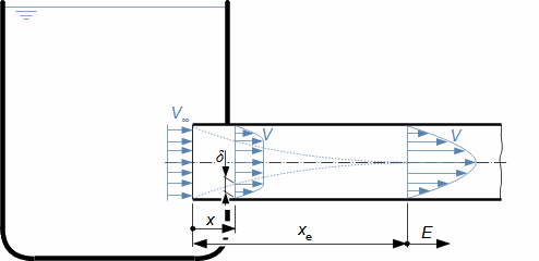
Characteristic features of fluid flowInternal frictionLoss heatVelocity profileBoundary layerPressure lossThe entropy of the flowing fluid increases, which is caused by the internal friction of the fluid, which causes part of its kinetic energy to be transformed into the internal energy of the fluid (referred to as the loss heat). Other effects of internal friction are pressure loss as the fluid flows through the channel and a lower flow velocity at the channel walls and a higher velocity at the channel center - the distribution of fluid velocity in the channel section under investigation is called the velocity profile. However, the velocity profile develops gradually. Figure 1 shows the gradual development of the fluid velocity profile in a pipe at the outlet of a vessel under the action of internal friction. The effect of internal friction starts at the inlet of the pipe, where the fluid friction against the walls of the channel occurs, this loss of kinetic energy of the fluid propagates away from the walls and thus the velocity profile gradually develops. Simultaneously, the flow velocity in the core of the flow increases to maintain flow continuity, as the velocity is conversely very low near the walls. The region affected by the existence of a wetted wall is called the flow boundary layer. In the case of closed channels, the boundary layers of opposite sides, as they continuously grow, merge after a certain length xe. 1: Rise and development of velocity profile in channel E-region of fully developed boundary layer. V [m·s-1] flow velocity at investigated location of channel; V∞ [m·s-1] flow velocity at inlet of channel section under investigation; x distance from inlet to pipe; xe [m] [m] entrance length (not completed boundary layer development); δ [m] boundary layer thickness.Ideal fluidFor the purpose of basic calculations of complex flow and comparison problems, we define an ideal fluid in which there is no internal friction and its heat capacity is constant. Ideal fluid flow models are closer to the actual flow the smaller the ability of the actual fluid to produce internal friction. |
Liquid heliumSuperfluidityThe closest to an ideal fluid is liquid Helium, which at temperatures below 2 K does not produce internal friction, this property is called superfluidity. Superfluidity also allows for the existence of opposing flows in the same channel without friction. Laminar flowTurbulent flowWilkens et al., 2009The development of the boundary layer and velocity profile is influenced by the type of flow. There are two types of flow according to the principle of interaction between the flow particles and the transfer of kinetic energy between them. These are laminar flow and turbulent flow. In laminar flow, the fluid forms parallel stream lines, and these lines slide over each other (the fluid forms tiny vortices within the lines). The fluid in neighbouring streamlines does not mix. In a turbulent flow, individual stream lines can no longer be identified and the motion of the elementary fluid particles is random. Figure 2 shows the trajectories of particles that are drifted by laminar flow and turbulent flow, see also the photographs in [Wilkens et al., 2009]. These particles are at the same time significantly more massive than the fluid molecules so that they cannot be affected by Brownian motion, but at the same time they are not significantly affected by gravitational acceleration. However, even in turbulent flow, lower velocities prevail near the walls and higher velocities in the core of the flow. Under what conditions laminar or turbulent flow can be expected is discussed in the chapter Laminar flow collapse and turbulent flow development. 2: The difference between laminar and turbulent flow (a) typical characteristics of laminar flow and its velocity profile; (b) typical characteristics of turbulent flow and its velocity profile.The theory of internal friction, respectively the boundary layer, explains the occurrence of pressure losses, the behaviour of the fluid when flowing through a pipe or the increase in drag when flowing around bodies. Four definitions of mean flow velocityA large number of fluid flow parameters are calculated from the mean flow velocity, which can be related to the velocity profile, to the mass flow, to the momentum of the fluid, or to the kinetic energy of the fluid. |
Velocity profileThe mean flow velocity derived from the velocity profile corresponds to the average value of the velocity profile, see Formula 3c. 3: Examples of velocity profiles and mean flow velocities (a) velocity profile between two plates in case of frictionless flow; (b) velocity profile between two plates of actual fluid. A [m2] flow area; ek [J·kg-1] mean fluid kinetic energy; M [N] fluid momentum in channel; m• [kg·s-1] mass flow; V [m·s-1] local fluid velocity; V‾ [m·s-1] mean flow velocity; y [m] coordinate perpendicular to flow direction.Mass flowThe mean flow velocity derived from the mass flow in the channel under investigation is defined by Formula 3d. It is the flow velocity at which the same amount of fluid corresponding to the mass flow rate flows through the channel per unit time - this is the most commonly used mean flow velocity. Fluid momentumThe mean flow velocity derived from the momentum of the fluid in the channel under investigation is defined by Formula 3e. It is therefore the fluid velocity at which it would achieve the same momentum (the force acting by the fluid stream on the perpendicular plate) as the actual fluid flow with the velocity profile. Kinetic energyThe mean flow velocity derived from the kinetic energy of the fluid in the channel under investigation is defined by Formula 3f. At this velocity, the flow would achieve the same power as the actual flow with the velocity profile. For the case of an incompressible fluid, the values of the mean velocity determined from the velocity profile and the mass flow are equal (V‾m=V‾profile). The second most commonly used definition of mean flow velocity in engineering practice is that based on the kinetic energy of the fluid - used in energy balances, for example, using the Bernoulli equation, in which the kinetic energy of the fluid comes out. |
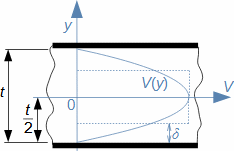
Three definitions of boundary layer thicknessThe thickness of the boundary layer is analysed in terms of its effect on the mass flow, momentum and energy of the investigated flow. From here we distinguish three characteristic boundary layer thicknesses, also see Problem 1. Displacement thicknessMass flowThe equivalent flow area through which the working fluid would flow at the maximum velocity and mass flow equal to the difference between the frictionless flow mass and the actual flow mass is called the displacement thickness, see Equation 4a. 4: Characteristic boundary layer thicknesses for case of flow between two plates (a) displacement thickness; (b) momentum thickness; (c) energy thickness; (d) definition of boundary of affected area in case of profile wrapping. A* [m2] flow area of displacement thickness; A** [m2] flow area of momentum thickness; A*** [m2] flow area of energy thickness; Vmax [m·s-1] maximum flow velocity; V∞ [m·s-1] attack velocity (velocity in front of profile). The equations are derived in App. 5.Momentum thicknessMomentumThe equivalent flow area through which the working fluid would flow at a maximum velocity with momentum equal to the difference between the frictionless fluid momentum and the actual fluid momentum is called the momentum thickness, see Equation 4b. Energy thicknessKinetic energyThe equivalent flow area through which a working fluid would flow at a maximum velocity of the same kinetic energy as the difference between the kinetic energy of the fluid in frictionless flow and the kinetic energy of the actual fluid is called the energy thickness, see Formula 4c. ProfileAttack velocityThe characteristic thicknesses of the boundary layer in the vicinity of the isolated profiles determine the attack velocity, while the boundary of the affected area to which the flow is determined is at a distance where the flow velocity is already very close to the velocity in front of the affected area (reaching 99% of the maximum velocity), see Figure 4d. |
The given definitions of characteristic thicknesses are used when comparing different types of channels with each other in terms of velocity, momentum and energy losses, because there are applications where, for example, the smallest possible momentum loss is important and in others, energy loss, etc. Definition of viscosity and its valuesThe influence of internal friction on the velocity profile in laminar flow can be qualified by a quantity called dynamic viscosity (abbreviated as viscosity). The viscosity values of the fluids under investigation are used to calculate flow parameters including pressure loss. ViscosityDynamic viscosityKinematic viscosityIssac NewtonDynamic viscosity is the ratio between the tangential stress and the velocity tensor, see definitional Equation 5. This definition was introduced by Issac Newton based on a simple experiment with internal fluid friction, which is described in Appendix 6. 5: Definition of viscosity F [N] frictional force acting on element; η [Pa·s] dynamic viscosity of working fluid; τ [Pa] shear stress between streamlines caused by frictional force (friction between streamlines); ν [m2·s-1] kinematic viscosity; S [m2] frictional area between investigated streamlines.Newtonian fluidNon-Newtonian fluidFluids for which the above definition of viscosity can be applied are called Newtonian fluids and, conversely, fluids in which the viscosity changes with velocity are called non-Newtonian fluids (fluids containing larger clusters of molecules such as colloidal solutions, suspensions, emulsions, gels, etc.). Newton's viscosity lawBird et al., 1965The definition of viscosity written by Formula 5 is based on the very simple case of plane flow. If we are investigating spatial flow, where the velocity profile changes in multiple directions, we must assume a tensor of tangential stresses in the fluid from internal fluid friction (see Problem 2). The relationship between the individual shear stresses and viscosity in spatial flow is called Newton's law of viscosity, which is given, for example, in [Bird et al., 1965] for different coordinate systems. |
Viscosity valuesViscometerViscosity of waterViscosity of airReduced viscosityCritical viscosityBird et al., 1965The dynamic viscosity of fluids is measured using viscometers, of which there are several types. The results of the measurements are entered into thermodynamic tables which are used in calculations. However, viscosity varies with temperature and pressure, complicating data collection. Dynamic viscosity of liquids decreases with temperature and increases with pressure, though the pressure effect is negligible except at extremely high pressures (megapascals). The dynamic viscosity of gases increases with temperature and is independent of pressure, except at extremely low or high pressures. For these reasons, dynamic viscosities of fluids for engineering purposes are given only as a function of temperature, see Tables 6, 7 for water and steam and Tables 9, 10 for dry and moist air. In the absence of data, the approximate viscosity can be calculated as the product of the reduced and critical viscosities. The reduced viscosity is a function of pressure and temperature, see charts in [Bird et al., 1965]. The critical viscosity is the viscosity of the substance at the critical point.
6: Viscosity of water at pressure of 101 325 Pa t [°C] temperature; η [μPa·s]; ν [nm2·s-1]. Values from 100 °C and above are for saturated water, i.e. at higher pressures corresponding to saturated liquids.
7: Viscosity of saturated steam t [°C]; η [μPa·s]; ν [nm2·s-1].
Viscosity of gas mixtureIn engineering practice, mixtures of gases or liquids are common, with viscosity depending on the molar concentrations of their components (see Equation 8 and Problem 3). 8: Equations for calculating viscosity of mixture ηi [Pa·s] dynamic viscosity of individual mixture component; δi [1] mole fraction of individual mixture component. The equation is valid for cases where the individual viscosities are independent of the partial pressures of the individual components. |
9: Dry air viscosity at 0,1 MPa t [°C]; η [μPa·s]; ν [μm2·s-1].
10: Viscosities of moist air at 0,1 MPa t [°C]; η [μPa·s]; ν [μm2·s-1]; ϕ [1] relative humidityLaminar flow equationThe fundamental parameters of laminar flow can be determined using the Navier-Stokes equation. The Euler equation of hydrodynamics is also a special form of the Navier-Stokes equation for the case of insignificant viscosity effects. In addition, the Navier-Stokes equation can be used to derive equations for pressure loss or loss heat for the case of channels of simple shapes, for example, Poiseuille law for pressure loss in a circular pipe, the relationship between mean velocities determined from mass flow and kinetic energy of the fluid, etc. Navier-Stokesova equationClaude-Louis NavierGeorge Gabriel StokesBird et al., 1965The amount of loss heat increases in the direction of flow, hence, and using the definition of viscosity, the equation of laminar fluid motion, also known as the Navier-Stokes equation, can be derived, see Equation 11. The Irish mathematician George Gabriel Stokes (1819-1903) is added in the title to honor him because he experimented further with the equation and described its possibilities in depth, although there were more scientists who developed it. |
11: Navier-Stokes equation g [m·s-2] gravitational acceleration; grad Lq [J·kg-1·m-1] gradient of loss heat ( amount of loss heat released in 1 kg of fluid when displaced 1 m in given direction); p [Pa] pressure; s→ [m] unit direction vector; V·∇)V [J·kg-1·m-1] change (gradient) of kinetic energy in flow direction. The equation is derived for the case of steady laminar flow of a viscous fluid at constant density in Appendix 7; for the general case of non-steady flow with variable density, the Navier-Stokes equation is derived in [Bird et al., 1965], where it is referred to as the equation of motion.Loss heatRe-used heatThe loss heat Lq is the cause of the increasing entropy of the fluid. The increase in the loss heat can occur not only during friction, but also during swirling between individual streamlines. In gases, part of the loss heat respectively internal thermal energy can be transformed back into pressure, kinetic or potential energy and work. This is due to the fact that the specific volume of the gas increases when the temperature increases. For this energy, the concept of re-usable heat is used in turbomachinery theory [Škorpík, 2024]. The loss heat equation also implies that a gas at very low density or pressure can have very high internal friction. Potential flowLaminar flow is not potential flow [Škorpík, 2023] because the curl of the velocity vector is different from zero, respectively the velocity vector is not a gradient of the potential quantity. However, the velocity of laminar flow is a potential quantity because it can be determined only by specifying the coordinates. Euler equation of hydrodynamicsThe Euler equation of hydrodynamics (Equation 12) is an equation derived from the force equilibrium of a fluid element without considering the effect of frictional forces on this element. It can be easily obtained from Equation 11 for the case that the left-hand side equals 0. From Equation 12, it is well seen that the scalar multiple of the velocity vector and the velocity divergence (V·∇)V is the fluid acceleration, which can be broken down into the form of Equation 12(left) as the sum of the velocity kinetic energy gradient and the velocity vector products - that is, laminar flow is not potential flow because in the case of potential flow, the acceleration is only equal to the kinetic energy gradient. 12: Euler equation of hydrodynamics The derivation of the Euler equation of hydrodynamics for vortex flow and the relation to potential flow are shown in Appendix 8. |
Poiseuille lawPipeGotthilf HagenJean PoiseuilleJohann NikuradseDeriving equations for the pressure loss and fluid velocity for laminar flow in channels of simple shapes is not difficult using the Navier-Stokes equation, see Problem 4 for flow between two plates and Equation 13 for a pipe. The equations for laminar flow through a circular flow area were first derived by the German engineer Gotthilf Hagen (1797-1884) and the French physicist Jean Poiseuille (1797-1869), hence they are sometimes referred to as Poiseuille law. The validity of this equation (except for very short sections) was confirmed by the German-Georgian engineer Johann Nikuradse (1894-1979). 13: Laminar flow parameters in pipe Lp [Pa] pressure loss on investigated length of pipe; l [m] length of pipe; re [m] inner radius of pipe; Q [m3·s-1] volumetric flow; r [m] distance of investigated radius from centre (axis) of pipe; V [m·s-1] axial velocity component (in direction of pipe axis). The relation is derived in Appendix 9 for the case of steady flow of incompressible fluid in a circular pipe, neglecting the effect of potential energy from the Navier-Stokes equation.Mean velocityKinetic energyThe derivation of the equations for the mean velocity of laminar flow according to their defining Equations 3 is easy for simple channel shapes, see Equation 13 and Equation 14 for the mean velocities in the pipe and laminar flow between two plates. 14: Relationship between mean velocity and kinetic energy (a) equation of mean velocity for laminar flow between two plates; (b) equation of mean flow velocity for laminar fluid through pipe. The equations were derived for a constant fluid density ρ=const. The derivation of the equations is shown in Appendix 10. |
Laminar boundary layer development and Reynolds numberVelocity profileEntrance lengthReynolds numberThe velocity profile along the length under investigation may not be constant, especially if it is the entrance section of the channel/pipe under investigation where the boundary layer has yet to develop, see Figure 1. The entrance length xe of the channel at which the boundary layer develops is a function of the channel shape and the ratio between the dynamic pressure and the shear stress in the fluid, which we refer to as the Reynolds number Re, see Equation 15. 15: Calculation of entrance channel length and Reynolds number Ch [m] entrance length coefficient; L [m] characteristic dimension; Re [1] Reynolds number (Re is added to formula for xe when boundary layer is fully developed) - formula for Reynolds number is derived in Appendix 11.Entrance length coefficientJoseph BoussinesqLudwig SchillerBauer, 1950Latif, 2006The values of the entrance length coefficient for a circular pipe are approximately in the range Ch≈0,025...0,065 - the value 0,065 was derived by the French physicist and mathematician Joseph Boussinesq (1842-1929), the value 0,025 by the German physicist Ludwig Schiller (1882-1961). It can be said that higher values correspond to shorter and lower to longer entrance sections (summarized in [Bauer et al., 1950, p. 143]). Ch factors for channels of non-circular flow area are given in [Latif, 2006, p. 208] and a selection in Table 16.
16: Entrance length coefficients of rectangular channels Ch [m]; h [m] longer side of rectangle; t [m] shorter side of rectangle.Characteristic dimension (Equivalent diameter)Wetted perimeterProfileChordThe characteristic dimension in Formulas 15 takes into account the dimension of the flow channel or wrapped body. It is the dimension to which any measurements are made. The characteristic dimension of closed channels is most often defined by Formula 17 - in the case of a circular flow area it is the diameter, therefore the characteristic dimension is also called the equivalent diameter. However, there are also a number of atypical cases where a different definition of the characteristic dimension is used. In general, the characteristic dimension of a body is the dimension that has the greatest influence on the flow (for example, in the case of blade profiles, it is the length of the chord). |
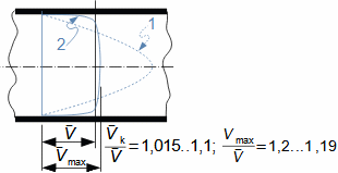
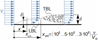
17: Definition formula of characteristic dimension of flow area A [m2] flow area; u [m] wetted circumference of channel (perimeter of channel flow area in contact with flowing fluid).Laminar flow collapse and turbulent flow developmentCritical velocityBetween the streamlines of laminar flow, a pair of forces acts on the fluid elements (see Figure 5), this pair of forces drives the elements into rotation. This means that a series of tiny vortices are formed between the streamlines, which dissipate their energy by friction, respectively their kinetic energy is constant, but at higher velocities the energy in the vortices gradually increases. Eventually, the vortices may gain such energy that they begin to disrupt the boundaries of the streamlines, causing the flow to mix and share energy. Turbulent flow occurs. The speed at which this occurs is called the critical velocity of laminar flow. At this velocity, the inertial forces of the particles dominate over the frictional force. Velocity profileMean velocityBird et al., 1965The turbulent velocity profile is characterized by the fact that it does not show such a significant difference between the velocity at the core and at the margins of the flow as the laminar velocity profile, see Figure 18. This is due to the migration of fluid particles and therefore kinetic energy throughout the flow area (see Figure 2). The shape of the turbulent flow velocity profile can be determined by the equations given, for example, in [Bird et al., 1965]. 18: Turbulent velocity profile in the pipe 1-velocity profile of laminar flow; 2-velocity profile of turbulent flow. Vmax [m·s-1] maximum velocity in turbulent profile. Data for velocity ratios [Maštovský, 1964, p. 78], [Mikula et al., 1974, p. 57].TurbulenceBoundary layerPipeThe critical flow velocity does not guarantee the existence of turbulence in the entire fluid volume under investigation. Turbulent flow develops from laminar flow as the inertial forces in the boundary layer increase, see Figure 20. For example, fully developed turbulent flow in a pipe is found only in the region of the pipe 10 to 60 pipe diameters away from the mouth [Jícha, 2001, p. 66]. |
TurbulizerFlow separationThe length of the section over which the flow begins to turbulise also depends on the geometry of the entrance, where the streamlines may interfere with the entrance edges, and also on the surface roughness. So-called turbulisers work on this principle to induce turbulent flow as early as possible, for example for the purpose of mixing the streams, or for the purpose of evenly distributing the kinetic energy of the stream as one of the measures to reduce the sensitivity to flow separation from diffuser walls, etc. 20: Development of turbulence during plate wrapping LBL-laminar boundary layer; TBL-turbulent boundary layer. δ [m] local thickness of boundary layer; x [m] distance from edge; xcrit [m] start of transition from laminar to turbulent boundary layer (formula according to [Latif, 2006, p. 296]).Critical Reynolds numberThe value of the critical velocity, at which the collapse of laminar into turbulent flow begins to occur, can be determined from the Reynolds number at which this process occurs, because the vortices will disrupt the streamline the greater the ratio of the dynamic pressure of the flowing fluid (inertial force) to the shear stress (frictional force) in the fluid. This value of the Reynolds number is called the critical Reynolds number ReC. PipeThe value of the critical Reynolds number for the pipe obtained by experiments is ReC=2320. However, it can be higher in some cases, so the range Re=2320 to Re=5000 to 6000 is referred to as the transition region. This means that at these values there is some probability for both laminar and turbulent flow. From Re=6000 onwards (the so-called upper critical Reynolds number) the flow is always turbulent. It should be noted that in practice these values will be lower, as the values given here are from measurements in laboratories on perfectly seated pipes without vibration.
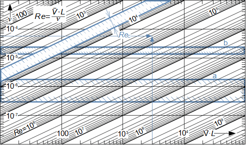
PipeFigure 19 is a nomogram for the calculation of the Reynolds number with the transition region in the pipe flow marked. The nomogram shows, among other things, that laminar flow normally occurs only at very high kinematic viscosities and low velocities - most likely to be encountered in small diameter ducts - otherwise the Reynolds numbers are significantly greater than the critical Reynolds number. |
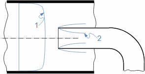
19: Nomogram for reading off Reynolds numbers V‾ [m·s-1]; L [mm]; ν [m2·s-1]; Re [1]. a-range of kinematic viscosities of water between 0 °C and 100 °C; b-range of kinematic viscosities of dry air between 0 °C and 100 °C. ReC [1] range of critical Reynolds numbers for pipe.Disappearance of turbulenceBoundary layerLaminar flowLaminar flow elementThe turbulent flow can revert to laminar flow if the Reynolds number drops below the critical Reynolds number. For example, if we embed a plate in a turbulent flow, a laminar boundary layer will form on both sides of the plate, see Figure 20. Another example is the change in pipe diameters, as indicated in Figure 21. In this case, a turbulent flow is sucked through an embedded pipe at the mouth of which a laminar boundary layer is formed which, if the Reynolds number is low enough in this channel, can merge to form a laminar profile throughout the flow area. The same effect of laminar layer formation can be observed in blade passage flow, even if the inlet flow is turbulent. The inserts in the flow in which a laminar layer is to be formed or maintained is called a laminar flow element. |
21: Transition of turbulent flow into laminar flow 1-fully developed turbulent profile; 2-areas of laminar boundary layer formation.ProblemsProblem 1:
Calculate the characteristic boundary layer thicknesses for the flow between two plates if the velocity profile were parabolic. Choose the maximum flow velocity, channel width, channel height and fluid density. The solution to the problem is shown in Appendix 1.
t [m] distance of plates; δ [m] characteristic thickness of boundary layer.
Symbol descriptions are in Appendix 1. Problem 2:
Determine the stress tensor in a fluid at laminar flow between two plates if the pressure p is at the point under investigation. The solution to the problem is shown in Appendix 2.
Problem 3:
Determine the viscosity of a mixture of nitrogen N2 and oxygen O2 under standard conditions. The mole fraction of nitrogen for this mixture is 0,785. The solution to the problem is shown in Appendix 3.
Symbol descriptions are in Appendix 3. |
Problem 4:
Determine the equations for loss heat, pressure loss and velocity for the case of steady fully developed laminar flow of an incompressible fluid between two plates. The solution to the problem is shown in Appendix 4.
ReferencesŠKORPÍK, Jiří, 2023, Technická matematika, engineering-sciences.education, Brno, [online], ISSN 1804-8293. https://engineering-sciences.education/technicka-matematika.html
ŠKORPÍK, Jiří, 2024, Termodynamika tepelných turbín, Transformační technologie, Brno, [online], ISSN 1804-8293. https://turbomachinery.education/termodynamika-tepelnych-turbin.html
BAUER, František, Oldřich BRŮHA a Zbyněk JAŇOUR, PEŠEK, Rudolf, ed., 1950, Základy proudění, Vědecko-technické nakladatelství, Praha.
BIRD, Byron, STEWART, Warren, LIGHTFOOT, Edwin, 1960, Transport phenomena, John Wiley & Sons, New York. (České vydání: BIRD, Byron, STEWART, Warren, LIGHTFOOT, Edwin, 1968, Přenosové jevy: sdílení hybnosti, energie a hmoty, Academia, Praha)
JÍCHA, Miroslav, 2001, Přenos tepla a látky, Vysoké učení technické v Brně, Brno, ISBN 80-214-2029-4.
LATIF, Jiji, 2006, Heat Convention, Springer-Verlag, Berlin, ISBN-10 3-540-30692-7.
MAŠTOVSKÝ, Otakar, 1964, Hydromechanika, Statní nakladatelství technické literatury, Praha.
MIKULA, Julius, KOČKA, Jaroslav, ŠKRAMLÍK, Emanuel, ŠTAUBER, Zdeněk, VESELÝ Adolf, OBR, Jan, 1974, Potrubí a armatury, Státní nakladatelství technické literatury, Praha.
WILKENS, Andreas; DREISEITL, Herbert; GREENE, Jennifer; JACOBI, Michael; LIESS, Christian SCHWENK, Wolfram, 2009, Wasser bewegt: Phänomene und Experimente, Haupt Verlag, Bern, ISBN 978-3258075211. (České vydání: Andreas; DREISEITL, Herbert; GREENE, Jennifer; JACOBI, Michael; LIESS, Christian SCHWENK, Wolfram, 2009, Voda v pohybu - úžas v nás: pozorování a pokusy, Malvern, Praha, ISBN: 978-80-7530-069-0)
©Jiří Škorpík, LICENCE
|