3.

MACH NUMBER AND HIGH VELOCITY FLOW EFFECTS

Jiří Škorpík, skorpik.jiri@email.cz
3.3 . . . . . . . . . . . . . .
3.4 . . . . . . . . . . . . . .
Pressure disturbance in subsonic flow – Pressure disturbance in supersonic flow – Hugoniot's theorem (Area-Mach number relation) – Shock waves
3.8 . . . . . . . . . . . . . .
3.9 . . . . . . . . . . . . . .
3.10 . . . . . . . . . . . . . .
3.12 . . . . . . . . . . . . . .
3.13 . . . . . . . . . . . . . .
3.14 . . . . . . . . . . . . . .
Subsonic and transonic flow – Sound and supersonic flow – Glauert-Prandtl rule – Airfoils for high velocities
3.18 . . . . . . . . . . . . . .
3.19 . . . . . . . . . . . . . .
3.20 . . . . . . . . . . . . . .
3.21 . . . . . . . . . . . . . .
3.2
Author:
ŠKORPÍK, Jiří, ORCID: 0000-0002-3034-1696
Issue date:           
January 2006, February 2023 (2nd ed.)
Title:
Mach number and high velocity flow effects
Journal:
Transformační technologie (transformacni-technolgie.cz; fluid-dynamics.education; turbomachinery.education; engineering-sciences.education; stirling-engine.education)
ISSN:
1804-8293

Copyright©Jiří Škorpík, 2006-2023
All rights reserved.

 MACH NUMBER AND HIGH VELOCITY FLOW EFFECTS
3.3

Basic concepts in high velocity flow

Mach number

Speed of sound

Compressibility

Mach number is defined as the ratio of the velocity of a flow to the velocity of propagation of sound in a fluid (speed of sound), see Equation 1. If the Mach number reaches a value at which the fluid can no longer be considered incompressible for a given application, then such a velocity is considered high in aerodynamics. This is because compressibility causes effects in the flow that do not occur in the flow of incompressible fluids or low Mach numbers. It is the general effects of the properties of compressible fluids in flow that are the subject of this article.

Definition of Mach number and speed of sound
1: Definition of Mach number and speed of sound
a [m·s-1] speed of sound in continuum under investigation; M [Mach] Mach number; p [Pa] pressure; r [J·kg-1·K-1] specific gas constant; T [K] absolute gas temperature (static temperature); V [m·s-1] velocity of body or flow; ρ [kg·m-3] density; κ [1] heat capacity ratio. The derivation of the equation for the speed of sound is given in Appendix 3.

Subsonic flow

Transonic flow

Sonic flow

Supersonic flow

If the Mach number is less than one (M<1) in the surroundings of the fluid point under investigation, then we speak of subsonic flows. If the value of Mach number in the surroundings of the fluid point under investigation is around 1, specifically in the range 0,8<M<1,3, then we speak of transonic flow - specifically when the Mach number is exactly 1 (M=1) we speak of sonic flow. If the value of Mach number is above 1 (M>1) in the whole surroundings of the fluid point under investigation, then we speak of supersonic flow.

Critical Mach number

Sometimes we come across the term critical Mach number, this number is related to some well-defined point within the fluid volume under investigation, and it is the Mach number at which the speed of sound or supersonic velocity is reached somewhere in the volume (for example, when the fluid is flowing around some bodies inside).

 MACH NUMBER AND HIGH VELOCITY FLOW EFFECTS
3.4

Effects of finite magnitude of speed of sound on stream continuity

Sound propagates through a compressible medium at the speed of sound a, making it impossible for changes in pressure and state variables to oppose flow direction at supersonic speeds. Thus, fundamental differences exist in pressure disturbance propagation between subsonic, sonic, and supersonic flow in channels or around bodies. Hugoniot's theorem mathematically describes these differences and explains shock wave formation as abrupt transitions between subsonic and supersonic flow.

Pressure disturbance in subsonic flow

Profile

The sound is also information about the pressure around the source of the disturbance, by means of which the compressible environment adapts to the source of the sound, for example in Figure 2, due to the propagation of the pressure disturbance, which is faster than the profile, the air is already spreading out (see the drawn streamlines) in front of the profile; the pressure disturbance propagating from the opening in the gas tank towards the inside of the tank causing the gas to flow towards the opening where the pressure is lower, etc. The speed of sound can, from this perspective, also be understood as the speed of propagation of information in a given environment.

Nature of subsonic flow
2: Nature of subsonic flow
S-source of pressure disturbance (source). The flow around the drawn profile is subsonic.

Sound wave

Sound intensity

Intensity gradient

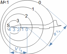
In a homogeneous environment, the pressure disturbance propagates from its source S in spherical surfaces, i.e. at the same velocity in all directions. The pressure difference at the boundary of the intact medium and the sound wave decreases with increasing radius of the sound wave (decreasing its energy density or sound intensity), thus also decreasing the influence of the sound wave on the surrounding medium. When the pressure disturbance source moves, the sound wave propagation velocity does not change only in the direction of movement of the pressure disturbance source the sound intensity gradient increases and vice versa, see Figure 3.

 MACH NUMBER AND HIGH VELOCITY FLOW EFFECTS
3.5
Propagation of sound waves when pressure disturbance source moves
3: Propagation of sound waves when pressure disturbance source moves
τ [s] time. The circles 0, 1, 2, 3 represent the boundary of sound waves in the environment at time τ=0...3. At time 0 the source is just at coordinate 0 at time 1 at coordinate 1 etc. This means that at point 0 the source will cause a pressure disturbance that propagates at the speed of sound in the spherical plane, after the source travels the distance 0-R it will have the radius of the sound wave indicated by the symbol 0 in the figure. The same procedure applies to the pressure disturbance induced by the source at point 1, etc.

Pressure disturbance in supersonic flow

Shock waves

If the source velocity approaches or exceeds the speed of sound in the compressible medium, discontinuities (abrupt state variable changes) occur. Instead of sound waves, pressure disturbances propagate as shock waves.

Shock wave angle

Mach angle

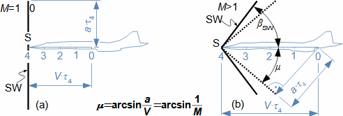
If the pressure disturbance source moves at or above the speed of sound (M≥1), its front is always at the source. This causes the streamlines to not gradually rise in front of the body being bypassed and the body is forced by its volume to displace the surrounding gas byabruptcompression - the energy to compress the gas in the shock wave is taken from the motion of the body. The gas thus compressed gradually expands away from the body. The boundary between the compressed gas and the surrounding gas is cone-shaped and is called a shock wave (Figure 4). The slope of the shock wave βSW is always greater than the Mach angle μ - their equality would occur for the case of an infinite body.

Relationship between shock wave angle and Mach angle
4: Relationship between shock wave angle and Mach angle
 MACH NUMBER AND HIGH VELOCITY FLOW EFFECTS
3.6
(a) source is moving at speed of sound - shock wave is slightly inclined forward; (b) source is moving at supersonic speed. SW-shock wave. βSW [°] slope of shock wave (μ<βSW); μ [°] Mach angle. The figure does not deal with the situation of the shock waves at the time before τ=0, nor with the situation behind the shock wave and behind the body; this problem is discussed in the next section of the paper.

Sound wave

Shock wave

Compared to a sound wave, the shock wave is a permanent abrupt change in state variables (higher pressure, temperature, and density behind it). This situation resembles an expanding ball of compressed gas, with more gas added due to body movement. However, the cone's volume increases with the third power of time, while the amount of compressed gas grows linearly (at constant velocity). Thus, shock wave intensity decreases with distance from the tip of the shock cone.

So far the propagation of sound waves or the generation of shock waves when a body is moving has been shown, but the same effect is achieved in the reverse case when the body is at rest and is surrounded by gas or a combination.

Hugoniot's theorem (Area-Mach number relation)

Pierre Henri Hugoniot

The equation predicting shock waves in compressible flow, including subsonic and supersonic behavior, was published in 1886 by French inventor, mathematician, and physicist Pierre Hugoniot (1851-1887). He developed it while studying flow at the mouth of gun barrels (see Equation 5).

Hugoniot's theorem (Area-Mach number relation)
5: Hugoniot's theorem (Area-Mach number relation)
A [m] flow area. This equation is referred to as Hugoniot's theorem or the Area-Mach number relation. The flow tube can be formed by solid walls or a sharp boundary between two media with very different states or properties (liquid versus gas; thin gas versus shock wave at the edge, etc.). The derivation of Hugoniot's theorem is given in Appendix 4.

Explanation of Hugoniot's theorem

According to Hugoniot's theorem, at the subsonic velocity at the inlet to the narrowing tube (M<1) there will be an increase in velocity and conversely, so it is also possible to determine the point in the tube where the flow can reach the speed of sound (M=1), it must be at the local extreme dA/A=0 - it remains to determine whether this is the minimum or maximum flow area of the tube.

 MACH NUMBER AND HIGH VELOCITY FLOW EFFECTS
3.7

Definition of critical speed

If the decrease in the velocity of the supersonic flow occurs only in the narrowing channel, then the speed of sound can only be achieved at the narrowest point of the channel. If this happens, we say that the flow has reached the critical velocity V* in the channel.

Supersonic nozzle

Supersonic diffuser

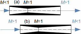
The behavior of the supersonic flow is therefore exactly opposite to that of the subsonic flow, which is why the two identical channels in Figure 6 operate quite differently in the subsonic and supersonic inlet flows. If the subsonic flow (Figure 6(a)) enters the channel and increases its velocity up to M=1 at the throat, beyond this cross-section the velocity increases further to a highly supersonic outlet velocity, then the channel shown behaves like a supersonic nozzle4.. Conversely, the channel shown behaves like a supersonic diffuser5., if a supersonic flow enters the channel, which decreases its velocity to M=1 at the throat, beyond which the velocity further decreases to the low subsonic velocity, thereby transforming the kinetic energy of the supersonic flow into compressive energy.

Examples of effect of inlet velocity on function of variable flow area
6: Examples of effect of inlet velocity on function of variable flow area
(a) supersonic nozzle (CD nozzle4.); (b) supersonic diffuser.

Shock waves

Machines in which supsonic velocities can occur can realistically only be designed for specific conditions (it can be shown that the ratio of the outlet flow area to the minimum flow area must also be different for different Mach numbers), changing the conditions would require changing the geometry of the machine to meet the requirements of the flow transition from supersonic to subsonic. This is often not possible to meet and the transition is made in the expanding part of the flow tube by the abrupt change in the state variables, i.e. the shock wave, only in this way can the conditions of Hugoniot's theorem be met ("smooth transition" is not possible in such a channel). There are several basic types of shock waves according to the conditions under which they are generated, see the following chapters.

 MACH NUMBER AND HIGH VELOCITY FLOW EFFECTS
3.8

Expansion waves

During the transition from subsonic to supersonic flow, there are no abrupt changes in the state variables, but so-called expansion waves occur, see below.

Normal shock wave

Normal shock wave equations

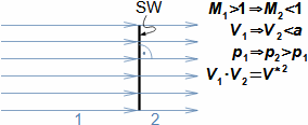
In normal shock wave, gas state variables change almost abruptly (its thickness is about 10-7 m [Hloušek, 1992]), see Figure 7. After passing through normal shock wave, the direction of flow remains the same, but the velocity is always lower than the speed of sound and momentum of the flow is decreasing. normal shock waves are generated in channels and around isolated bodies at the speed of sound.

Passage of gas by normal shock wave
7: Passage of gas by normal shock wave
1-gas state before shock wave; 2-gas state after shock wave. p [Pa] pressure; V* [m·s-1] critical flow velocity. The derivation of the equations for normal shock wave is carried out, for example, in [Macur, 2010, p. 372].

Ludwig Prandtl

Shock wave losses

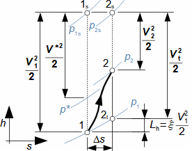
The energy balance of normal shock wave was first established with a satisfactory result by the German physicist Ludwig Prandtl (1875-1953) by introducing the assumption that losses occur in the shock wave during a abrupt change in the state variables, which had not been assumed until then. This means that the gas behind normal shock wave has higher entropy than that in front of it, which can be clearly seen from the h-s diagram of the shock wave in Figure 8.

Change of gas state when passing through normal shock wave
8: Change of gas state when passing through normal shock wave
 MACH NUMBER AND HIGH VELOCITY FLOW EFFECTS
3.9
h [kJ·kg-1] gas enthalpy; s [J·kg-1·K-1] gas entropy; Lh [J·kg-1] shock wave loss; p* [Pa] critical pressure (pressure when flow hits speed of sound during expansion from point 1s); Vt [m·s-1] theoretical gas velocity during isentropic expansion from pressure p2s to pressure p1; ξ [1] proportional shock loss. Index s denotes total state.

Rankine-Hugoniot equations

The shock wave loss depends solely on gas properties and velocity, as evident from Rankine-Hugoniot equations (Equation 9) and Problem 1 calculation. It's independent of the bypassed body's shape.

Rankine-Hugoniot equations
9: Rankine-Hugoniot equations
The equations are derived for the stable normal shock wave and ideal gas. The derivation of the equations is done in Appendix 5.

Oblique shock waves

States around oblique shock wave

Flow deflection

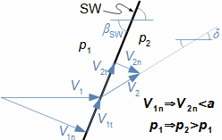
Before the oblique shock wave, velocity must be supersonic, but afterward, it can be subsonic or supersonic. As the flow traverses the oblique shock wave, its direction is deflected by angle δ (Figure 10). Normal velocity components (V1n, V2n) share properties with those passing through a normal shock wave (see Problem 2). The equality of tangential velocity components (V1t=V2t) can be proved (e.g., [Kadrnožka, 2004, p. 126-127]).

Passage of compressible medium by oblique shock wave
10: Passage of compressible medium by oblique shock wave
δ [°] velocity deflection post-shock from original direction. The index n denotes the normal velocity components, the index t denotes tangential velocity components.

Shock wave angle

Shock wave losses

Mach angle

Sound wave

Additionally, analyzing oblique shock wave properties reveals that when βSW equals the Mach angle μ, V1n=a1 must be true, indicating only the sound wave—following the Mach angle definition. It's also demonstrated that the maximum energy loss (entropy increase) happens when βSW=90°, making losses in the oblique shock wave less than in a normal shock wave for the same pressure ratio ahead and behind the wave.

 MACH NUMBER AND HIGH VELOCITY FLOW EFFECTS
3.10

Formation of oblique shock wave

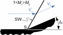
The oblique shock wave is generated, for example, on the edges of airfoils moving at supersonic velocities or when they are bypassed by the supersonic flow, see below. An oblique shock wave can also be created by an roughness on the contact surface (manufacturing roughness, a droplet of incompressible fluid in the supersonic flow, etc.) or by an interface between the supersonic flow and the surrounding environment, a typical example being the supersonic outlet of gas from the CD nozzle. The oblique shock wave also arises where the cross-sectional area of the supersonic flow is abruptly reduced, as shown in Figure 11. In a similar way, the oblique shock wave can also be generated when two supersonic flows meet obliquely, as indicated in Figure 19. If the surface angle δS is greater than the corresponding shock wave angle δ in Figure 10, then the shock wave will move before the beginning of the wedge [Dejč, 1967, p. 150]. An interesting situation occurs if the abruptly rising surface is replaced by an arc, see the following chapter.

Formation of oblique shock wave at heel of abruptly rising contact surface
11: Formation of oblique shock wave at heel of abruptly rising contact surface
δS [°] angle of contact surface.

Rocket engine

N2O4

The change in direction of the flow as it passes through the shock wave is used to deliberately change the direction of the supersonic flow, for example to control the thrust vector of solid rocket engines. In this case, the shock wave is created by a droplet of incompressible liquid (e.g. N2O4) injected on the inside of the nozzle. The shock wave is initiated at this droplet boundary.

Unreachable compression waves

Compression wave

The compression wave is an equivalent to the shock wave. It is smooth isentropic compression of supersonic flow in a narrowing space as described by Hugoniot's theorem. In practice, however, this process is not possible because the reduction of the flow area would have to be infinitesimal [Dejč, 1967, p. 405].

 MACH NUMBER AND HIGH VELOCITY FLOW EFFECTS
3.11

Crossed shock waves

In actual supersonic compression, instead of compression waves, crossing oblique shock waves are produced with gradually increasing wave angle (Figure 12). At the point of crossing, the effects of these shock waves, i.e. momentum and pressure, are summed. When several shock waves cross successively, their effect is added further away from the body and the resulting wave has even a smaller angle βSW than the first wave corresponding to a certain flow velocity.

Crossed shock waves
12: Crossed shock waves
(a) rising surface; (b) formation of compression waves at gradually rising surface [Nožička, 2000]. CW-set of compression waves.

Shock wave division

In aviation, experiments have been carried out to reduce the sound effects caused by shock waves in supersonic flights based on the division of the shock wave into several partial waves (shock wave dilution, see Figure 13). This not only reduces the losses in the shock waves, but most importantly, it maximizes the angle of the resulting shock wave (after all shock waves from the fuselage have met). This is because the larger the angle of the shock wave (preferably 90°), the smaller the sound effect from the wave [Hošek, 1962, p. 60] - which would allow transport aircraft to fly at high speeds even over populated areas.

Project Quiet Spike
13: Project Quiet Spike
The project successfully explored the possibility of reducing the intensity of sound effects by using a stepped extension of the aircraft's nose. Here, testing of the telescoping nose of F-15B aircraft [Creech, 2009].
 MACHOVO ČÍSLO A EFEKTY PŘI PROUDĚNÍ VYSOKÝMI RYCHLOSTMI
3.12

λ-shock wave

Formation of λ-schock wave

Transonic flow

Boundary layer

Laminar flow

Turbulent flow

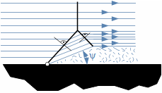
The λ-shock wave (Figure 14) forms when bodies are flown around at transonic velocity with a laminar boundary layer. In this layer, pressure gradually rises at the expense of velocity due to subsonic flow, increasing thickness. This creates a wedge, leading to oblique shock waves crossing, as shown in the simplified diagram (Figure 15). The resulting shock wave is often slightly inclined forward [Hošek, 1949]. In turbulent flow, the wedge is small (turbulent flow is less sensitive to pressure change), generating a directly normal shock wave at the boundary layer interface.

Simplified description of λ-shock wave
14: Simplified description of λ-shock wave
(a)-overall view of λ-shock wave; (b) pressure change in λ-shock wave and in the boundary layer. LBL-laminar boundary layer; i-pressure distribution in the core of flow before and after shock wave; ii-pressure distribution in the laminar boundary layer; OSW-oblique shock waves due to the increase in thickness of boundary layer. t [m] thickness of the boundary layer; x [m] distance from leading edge of airfoil.

Boundary layer separation

Generally, the loss in the λ-shock wave is less than in a normal shock wave and greater than in an oblique shock wave [Hošek, 1949, p. 201]. Therefore, streamlines passing through oblique shock waves (the part closer to the profile) will have a different velocity than those passing through a normal shock wave. Additionally, the loss by the boundary layer separation, occurring behind the λ-shock wave [Hošek, 1949, p. 198], [Kadrnožka, 2004, p. 132], must be considered (see Figure 14).

Boundary layer separation behind λ-shock wave
15: Principle of Boundary layer separation behind λ-shock wave
 MACHOVO ČÍSLO A EFEKTY PŘI PROUDĚNÍ VYSOKÝMI RYCHLOSTMI
3.13

Expansion waves

Formation of expansion waves

If the supersonic flow enters a space with increasing cross section it must expand to the higher velocity as predicted by Hugoniot's theorem. Such supersonic expansion takes the form of expansion waves.

Flow deflection

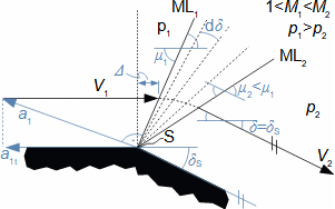
Increasing cross-sectional area also creates obtuse angles on bodies, like the trailing edge of projectiles, the beginning of fuselage taper, etc., as seen in Figure 16, illustrating a typical supersonic obtuse angle flow. When flying around obtuse angles at supersonic velocity, gas must expand from pressure p1 to p2, flow velocity increases from V1 to V2, and the gas direction is deflected by angle δ from the original. In the expansion wave, there's a gradual change in state variables with very low losses (isentropic expansion).

Supersonic flow near obtuse angle
16: Supersonic flow near obtuse angle
ML-Mach line; Δ [m] length difference.

Mach wave

Prandtl-Meyer function for flow deflection

The formation of the expansion wave in Figure 16 is initiated by the pressure disturbance at the edge S, which propagates upward with velocity a1t. The ML1 boundary at which flow direction starts to change and the gas starts to expand is so-called Mach line or also the first expansion wave. It is obvious that the slope of this line is equal to the Mach angle μ1. During expansion the Mach number changes and the expansion also changes its character because the Mach angle changes. The expansion stops at the Mach line ML2 where the flowing gas reaches pressure p2. The first and last Mach lines form the Mach wedge in which the gas expansion takes place. The value of the angle δ can be determined from the Prandtl-Meyer function ν [Anon., 2010], see Equation 17.

 MACH NUMBER AND HIGH VELOCITY FLOW EFFECTS
3.14
Prandtl-Meyer function
17: Prandtl-Meyer function
ν(M) [°] Prandtl-Meyer function

Maximum flow deflection

The maximum angle of deflection of the flow when passing through the expansion wave δmax and the maximum velocity V2max is reached by the flow when expanding into the vacuum p2=0. In vacuum expansion, M2=∞. If the angle of inclination of the edge is greater than δmax a vacuum will be created behind the edge S between the flow and the contact surface.

Beveled nozzle

Expansion waves can also be generated by supersonic flows in channel outlets, for example in beveled nozzles4. and supersonic blade channel outlets.

Effect of high velocities on airfoil aerodynamics

The difference between subsonic and supersonic flow around the airfoil is both in the velocity distribution and in the magnitude of the aerodynamic quantities describing the force effects of the flow on the airfoil. Hence the differences in the shapes of subsonic and supersonic airfoils.

Subsonic and transonic flow

λ-shock wave

Expansion waves

The velocity in the around of the airfoil first increases up to the widest its section, then starts to decrease and no effects are observed in the subsonic flow, see Figure 18(a). At the critical Mach number, the velocity may reach the speed of sound at some point in the around of the airfoil, causing expansion waves to form behind the widest section of the airfoil, behind which the velocity is higher than in front of them. Before the trailing edge of the profile, the shock wave will formed because the velocity at the end of the profile must again be subsonic to maintain flow continuity (continuous transition is not possible), and because for short profiles the boundary layer is laminar, this shock wave will be a λ-shock wave, see Figure 18(b).

Characteristics of subsonic flow around lenticular airfoil
18: Characteristics of subsonic flow around lenticular airfoil
(a) subsonic flow around airfoil; (b) transonic flow around airfoil, [Kneubuehl, 2004, p. 78]. EF-expansion fan; λW-λ-shock wave.
 MACH NUMBER AND HIGH VELOCITY FLOW EFFECTS
3.15

Sound and supersonic flow

Normal shock wave

Oblique shock wave

The λ-shock wave moves with increasing velocity towards the trailing edge of the airfoil. When the flow in front of the airfoil reaches the speed of sound, this wave is generated at the trailing edge and normal shock wave starts to form at the leading edge (Figure 19(a)). At supersonic velocity, the frontal normal shock wave transforms into the oblique shock wave and the same happens at the trailing edge where two oblique shock waves are formed by the collision of two supersonic streams from the suction and pressure sides of the airfoil, see Figure 19(b).

Flow around lenticular airfoil by sound and supersonic flow
19: Flow around lenticular airfoil by sound and supersonic flow
(a) flow around profile at sound speed in front of airfoil; (b) supersonic flow around profile [Kneubuehl, 2004, p. 78].

Space shuttle launch

The effects in the above paragraphs are observed as the body moves from take-off to high supersonic speed. Figure 20 displays the Space Shuttle Discovery launch (STS-114, 2005). On the left, the image at 50.87 s after launch (Mach 1.2, aerodynamic drag at max), on the right, at 59.72 s (Mach 1.5, aerodynamic drag decreasing).

Compressible flow around space shuttle at launch
20: Compressible flow around space shuttle at launch
Photo source [O’Farrell and Rieckhoff, 2011].

Glauert-Prandtl rule

Lift coefficient

Pressure coefficient

Drag coefficient

Laminar airfoil

The Glauert-Prandtl rule converts aerodynamic quantities from incompressible flow measurements to compressible flow using Equation 21. These equations are valid only up to critical Mach or Reynolds numbers [Abbott and Doenhoff, 1959, p. 256 and pp. 283-287], [Hošek, 1949, p. 52]. Profiles with flows below the critical Reynolds number are termed laminar profiles. These equations align with experimental measurements.

 MACH NUMBER AND HIGH VELOCITY FLOW EFFECTS
3.16
Glauert-Prandtl rule
21: Glauert-Prandtl rule
(a) Glauert-Prandtl rule for pressure coefficient; (b) Glauert-Prandtl rule for lift coefficient; (c) effect of increasing velocity on drag coefficient. CD& [1] drag coefficient of airfoil; CL [1] lift coefficient of airfoil; M [Mach] Mach number (before airfoil); CP [1] pressure coefficient of airfoil. The index i indicates incompressible flow, the index c compressible flow. The derivation is given in [Hošek, 1949, p. 49].

Lift coefficient

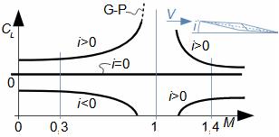
The Glauert-Prandtl rule is used from roughly Mach 0,3, and its accuracy decreases near the speed of sound, as the calculation results go to infinity, see Figure 22, in contrast to the measured values (see measurements in [Hošek, 1949, p. 345]).

Changes in lift coefficient for rhombic airfoil
22: Changes in lift coefficient for rhombic airfoil
i [°] angle of attack.

Drag coefficient

The change in the CD drag coefficient occurs only at transonic velocities, when λ-shock waves are generated. After leaving the transonic region, when oblique shock waves are generated, the drag coefficient decreases again, as shown in the example of flow around the Shuttle fuselage in Figure 19.

Angle of attack

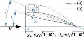
The Glauert-Prandtl rule can also be used in reverse - it is possible to determine how the thickness of the airfoil and the angle of attack of the airfoil should change at high speeds in order to have the same aerodynamic properties as at low speeds, see Equation 23, [Hošek, 1949, p. 57].

Practical application of Glauert-Prandtl rule
23: Practical application of Glauert-Prandtl rule
(a) airfoil in incompressible flow; (b) airfoil in compressible flow. x [m] airfoil coordinates in direction of inflow velocity; yi, c [m] airfoil thickness.
 MACH NUMBER AND HIGH VELOCITY FLOW EFFECTS
3.17

It is evident from the above that thin, slightly curved airfoils are sufficient for higher speeds, as anyone will notice in supersonic fighter aircraft, which are slimmer than subsonic machines.

Airfoils for high velocities

Aerodynamics of flight

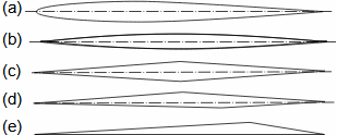
In a well-designed airfoil, the occurrence of high velocity effects and their effect on the aerodynamics of flight should be predictable. The rhombic airfoil is a good predictor in this respect. Expansion waves are only generated at the tips of the suction and pressure sides, and λ-shock waves are generated at the trailing edge of the airfoil. Of course, this profile is not suitable for low subsonic velocities, so various compromises of profile shapes are found depending on the velocities for which they are primarily intended, see Figure 24.

Profile types suitable for high speeds in compressible flow
24: Profile types suitable for high speeds in compressible flow
(a) transonic airfoil; (b) supersonic (lenticular shape); (c) supersonic (rhombic shape); (d) supersonic (trapezoidal shape); (e) hypersonic.

Point of lift

Point of drag

High velocities also cause a shift of the center of lift, which shifts with a change in Mach number [Hošek, 1949, p. 46, 240], and the magnitude of the lift changes simultaneously, see Figure 22. For this reason, modern airplanes are equipped with devices to change the geometry of the wing or shift the center of gravity, and especially at speeds around the speed of sound, they change the pitch to maintain such angles of attack as to keep the lift at the required magnitude - at very high subsonic speeds it can even be negative [Stever and Haggerty, 1966, Flight, p. 69].

 MACH NUMBER AND HIGH VELOCITY FLOW EFFECTS
3.18

Aerodynamics of profile cascades in compressible flow

Interferogram

Expansion waves

Flow deflection

Shock waves

Compressible flow effects at high velocity also manifest in profile cascade. Figure 25 shows an interferogram (photograph showing the changes in gas density) of supersonic flow through a turbine profile cascade, with inlet velocity at Mach 1.19 and outlet velocity at Mach 2.003 in isentropic flow. Visible are expansion waves around the cascade outlet and shock waves forming at the trailing edge where two supersonic flows meet. These waves alter the flow direction, a common issue at the supersonic flow exit of a profile cascade. Supersonic flow at the inlet generates oblique shock waves at the leading edges of the profiles.

Supersonic flow in blade cascade
25: Supersonic flow in blade cascade
left-scheme of situation recorded on interferogram; right-interferogram of supersonic flow through turbine profile cascade. Taken with Mach-Zehnder interferometer. Taken and images provided by Aerodynamic Laboratory in Nový Knín at Institute of Thermomechanics of AVČR, v.v.i.
Examples of numerical modelling of compressible flow in blade cascade
26: Examples of numerical modelling of compressible flow in blade cascade
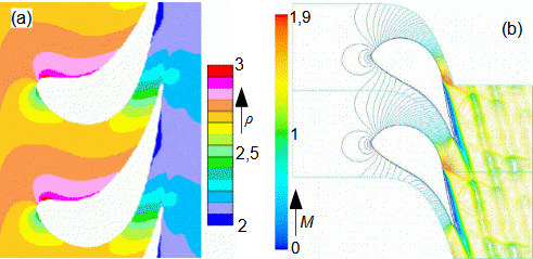
(a) water vapour M1=0.42 (in front of cascade), M2=0.7 (behind cascade), created at the Energy Institute of Brno University of Technology; (b) turbine blade cascade, working gas air [Tajč et al., 2007]. M [Mach]; ρ [kg-m-3] density.
 MACH NUMBER AND HIGH VELOCITY FLOW EFFECTS
3.19

Analytical calculation

Nozzles

Diffusers

A closed-form analytical solution can be found for compressible flow in the profile cascade only for the case of one-dimensional compressible flow in the channel - this is equivalent to the analytical solution of nozzles4. or diffusers5.. More accurate results that take into account the spatial nature of the flow can be achieved by numerical modelling using powerful computational hardware and appropriate software, see Figure 26.

Problems

Problem 1:

Shock wave losses

Convergent-divergent nozzle

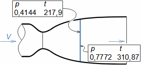
A normal shock wave was generated in the CD nozzle. Calculate the loss as the gas passes through this wave. The measured pressure and temperature before and after the wave are shown in the accompanying figure. The calculated velocity before the wave from the nozzle cross section and mass flow rate is 583.72 m·s-1. Dry air flows through the nozzle. The solution to the problem is shown in Appendix 1.
Průchod plynu kolmou rázovou vlnou
p [MPa]; t [°C].
§1   entry:   V1; t1; p1; p2; t2
§2   read off:   h1; h2t
  calculation:   Lh
The procedure for solving Problem 1. Symbol descriptions are in Appendix 1.
Problem 2:

Shock wave angle

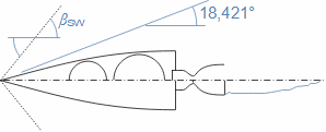
What is the angle of the shock wave created by a missile at M=2,5 Mach? Find the velocity, temperature and pressure in the stream behind the wave? The geometry of the missile is shown in the figure. The other parameters are: κ=1.4, t1=20 °C, p1=101 325.25 Pa, r=287 J·kg-1·K-1. The solution to the problem is shown in Appendix 2.
Flying missile and its shock wave
 MACH NUMBER AND HIGH VELOCITY FLOW EFFECTS
3.20
§1   entry:   δSMκt1p1r; Cp §4   calculation:   M2n; t2; V2t
§2   estimate:   βSW §5   compare:   V1t vs. V2t, if it differs more than allowed accuracy, then make new estimate of βSW and repeat calculation from §2
§3   calculation:   V1t; M1n §6   calculation:   V2; p2
The procedure for solving Problem 2. Symbol descriptions are in Appendix 2.

References

ŠKORPÍK, Jiří, 2019, Technická termomechanika, Transformační technologie, Brno, [on-line], ISSN 1804-8293. https://www.transformacni-technologie.cz/43.html.
ŠKORPÍK, Jiří, 2023, Technická matematika, Transformační technologie, Brno, [online], ISSN 1804-8293. https://engineering-sciences.education/technicka-matematika.html.
ŠKORPÍK, Jiří, 2022, Essential equations of turbomachines , Transformační technologie, Brno, [on-line], ISSN 1804-8293. Dostupné z https://turbomachinery.education/essential-equations-of-turbomachines.html.
ABBOTT, Ira, DOENHOFF, Albert, 1959, Theory of wing sections, including a summary of airfoil data, Dover publications, inc., New York, ISBN-10:0-486-60586-8.
ANON., 2010, Expansion fan – Isentropic flow, National Aeronautics and Space Administration – NASA, Washington, D.C., http://www.grc.nasa.gov.
CREECH, Gray, 2009, Supersonic Jousting, National Aeronautics and Space Administration – NASA, Washington, D.C.
DEJČ, Michail, 1967, Technická dynamika plynů, SNTL, Praha.
HLOUŠEK, Jiří, 1992, Termomechanika, Vysoké učení technické v Brně, Brno, ISBN 80-214-0387-X.
HOŠEK, Josef, 1949, Aerodynamika vysokých rychlostí, Naše vojsko, Praha.
HOŠEK, Josef, 1962, Dnešní letectví: nové vývojové směry v letectví, Práce, Praha
KADRNOŽKA, Jaroslav, 2004, Tepelné turbíny a turbokompresory, Akademické nakladatelství CERM, s.r.o., Brno, ISBN 80–7204–346–3.
KNEUBUEHL, Beat, 2004, Balistika střely, přesnost střelby, účinek, Naše vojsko, Praha, ISBN 80-206-0749-8.
MACUR, Milan, 2010, Úvod do analytické mechaniky a mechaniky kontinua, Vutium, Brno, ISBN 978-80-214-3944-3.
NOŽIČKA, Jiří, 2000, Osudy a proměny trysky Lavalovy, Bulletin asociace strojních inženýrů, č. 23, ASI, Praha.
O’FARRELL, J.M., RIECKHOFF, T.J., 2011, Direct Visualization of Shock Waves in Supersonic Space Shuttle Flight, George C. Marshall Space Flight Center, AL 35812 – Technical Memorandum.
STEVER, Guyford, HAGGERTY James, 1966, Flight, Time Inc.
TAJČ, Ladislav, BEDNÁŘ, Lukáš, POLANSKÝ, Jiři, Šťastný, Miroslav, 2007, Radial Control Stage with Partial Steam Admission, Proceedings of the 8th International Symposium on Experimental and Computational Aerothermodynamics of Internal Flows, Lyon.
©Jiří Škorpík, LICENCE