FLOW OF GASES AND STEAM THROUGH NOZZLES
page 4.4
|
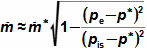
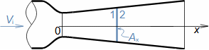
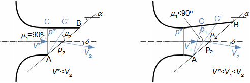
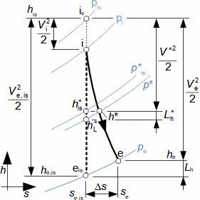
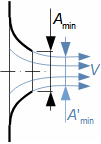
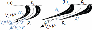
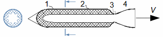
– 101: – 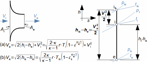 (a) calculation from the static gas state in front of the nozzle; (b) calculation from the total gas state in front of the nozzle. e-state at the nozzle outlet; i-state at the nozzle inlet. A [m2] flow area of nozzle; h [J·kg-1] enthalpy; p [Pa] pressure; r [J·kg-1·K-1] specific gas constant; s [J·kg-1·K-1] entropy; T [K] absolute gas temperature; t [°C] temperature; V [m·s-1] velocity; ε [1] pressure ratio of static pressures (pe·p-1i); εs [1] pressure ratio to stagnation inlet pressure (pe·p-1is); κ [1] heat capacity ratio. The index s indicates the stagnation state of the gas, the index i indicates the state at the nozzle inlet, the index e indicates the state at the nozzle outlet (just inside the nozzle outlet). The derivation of the equation is given in Appendix 101.
– 514: – 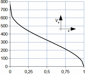 pat [Pa] atmospheric pressure. Gas parameters: κ=1,4, r=287 J·kg-1·K-1, ti=20 °C, pi=pat, Vi=0. Chart for ideal gas.
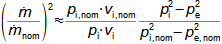
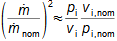
– 334: – 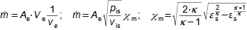 m• [kg·s-1] Mass flow through nozzle; v [m3·kg-1] specific volume; χm [1] outlet coefficient. The derivation of the equation for calculating the mass flow through the nozzle is shown in Appendix 334. |